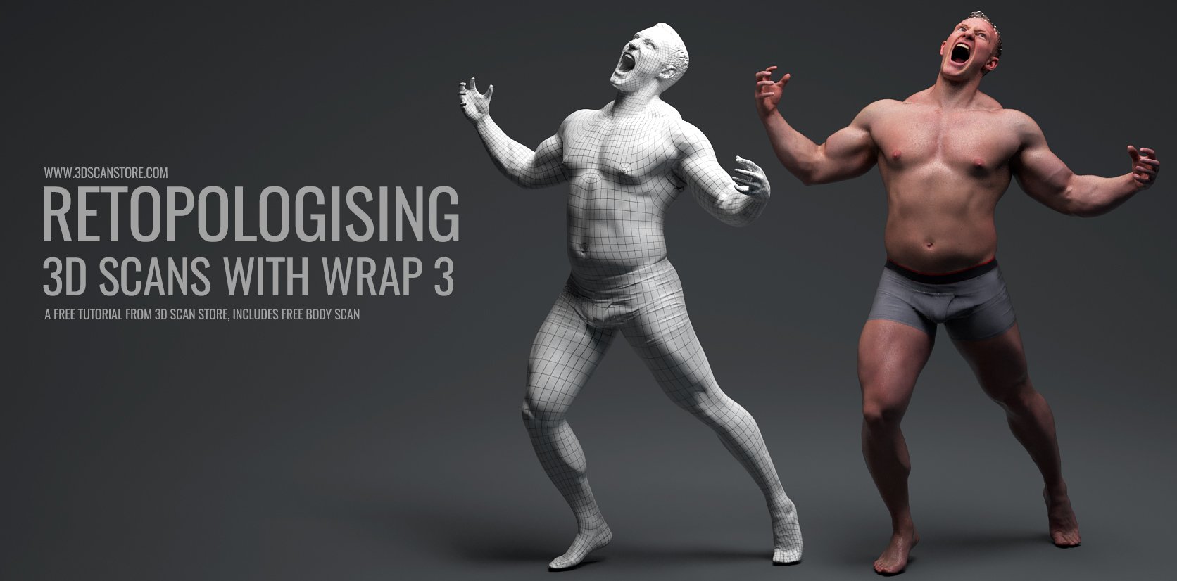
Retopologising 3D Scans with Wrap 3
By James Busby
In this tutorial, I want to show you a very quick and effective way of retopologising scan data using the excellent wrap 3 available using the link below, there's a 15 day free trial for those who want to give it a go. Wrap 3, in my opinion, is a must-have tool when working with scan data, quick and easy retopology using a good base mesh makes cleanup and editing so much easier compared to working with Zremeshed or dynameshed objects.
Method
Zbrush mesh preparation
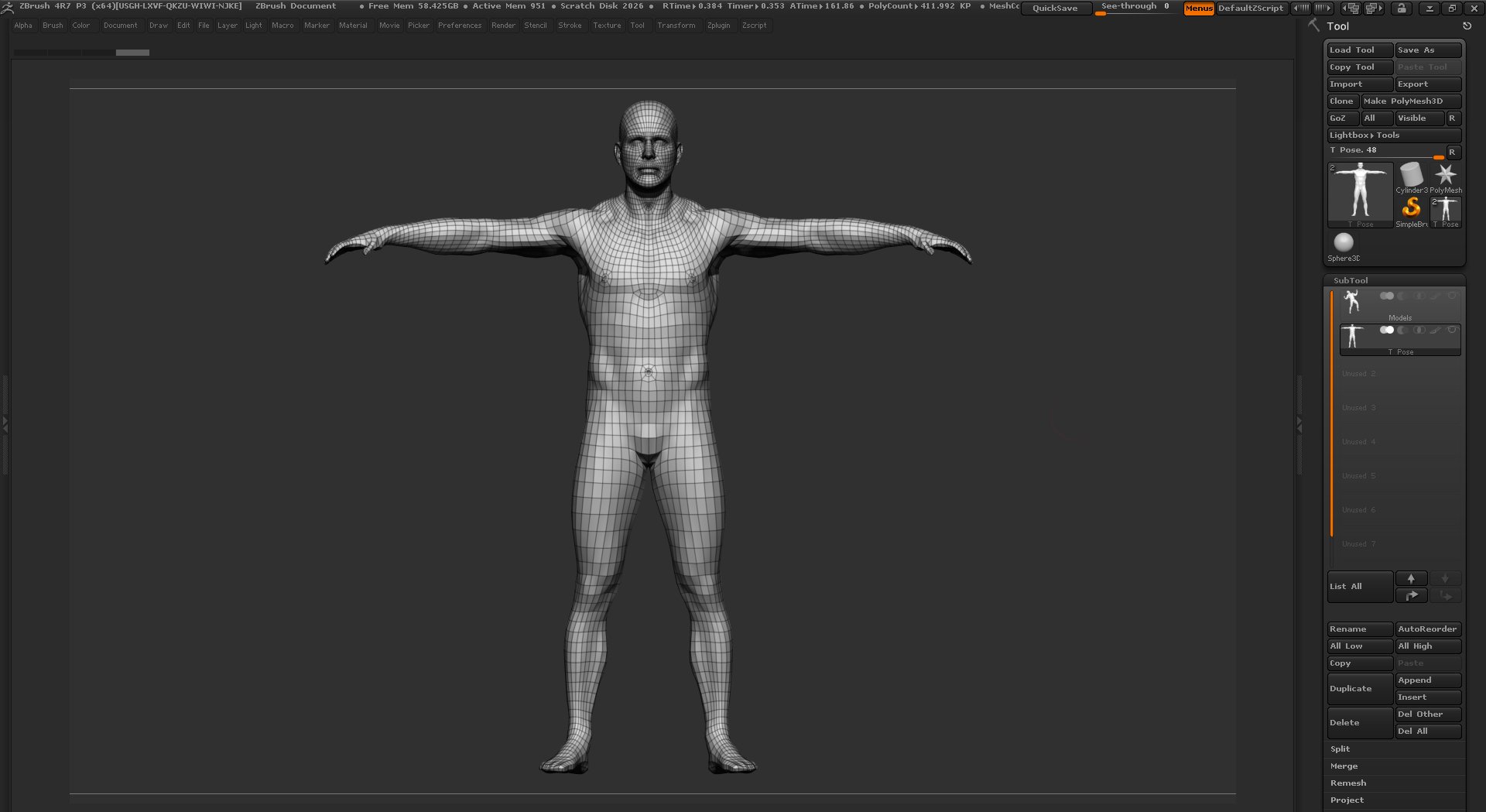
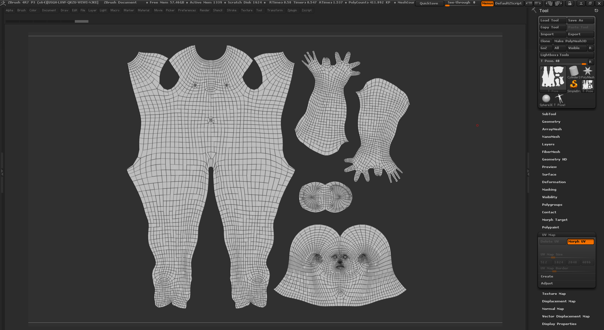
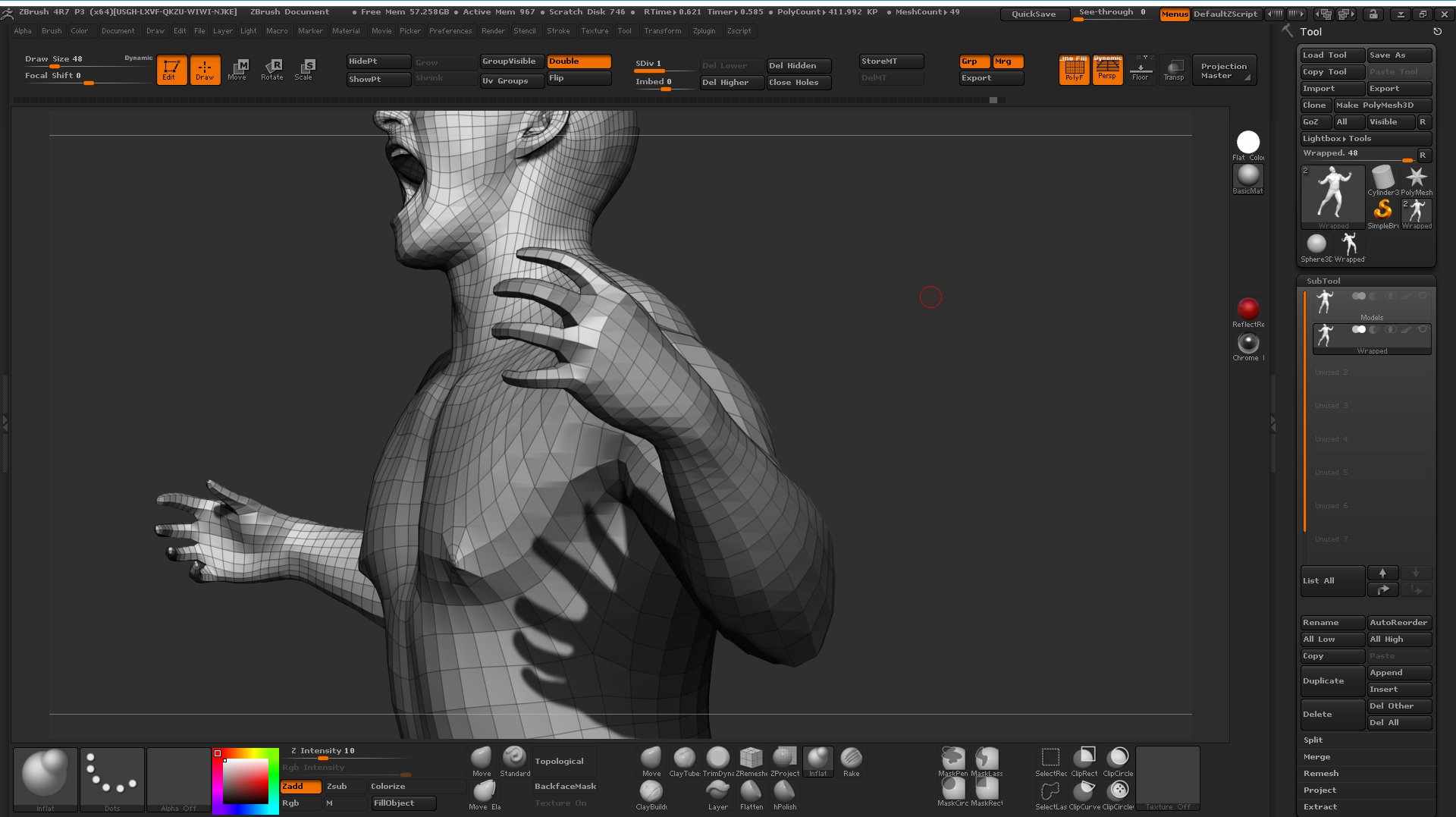
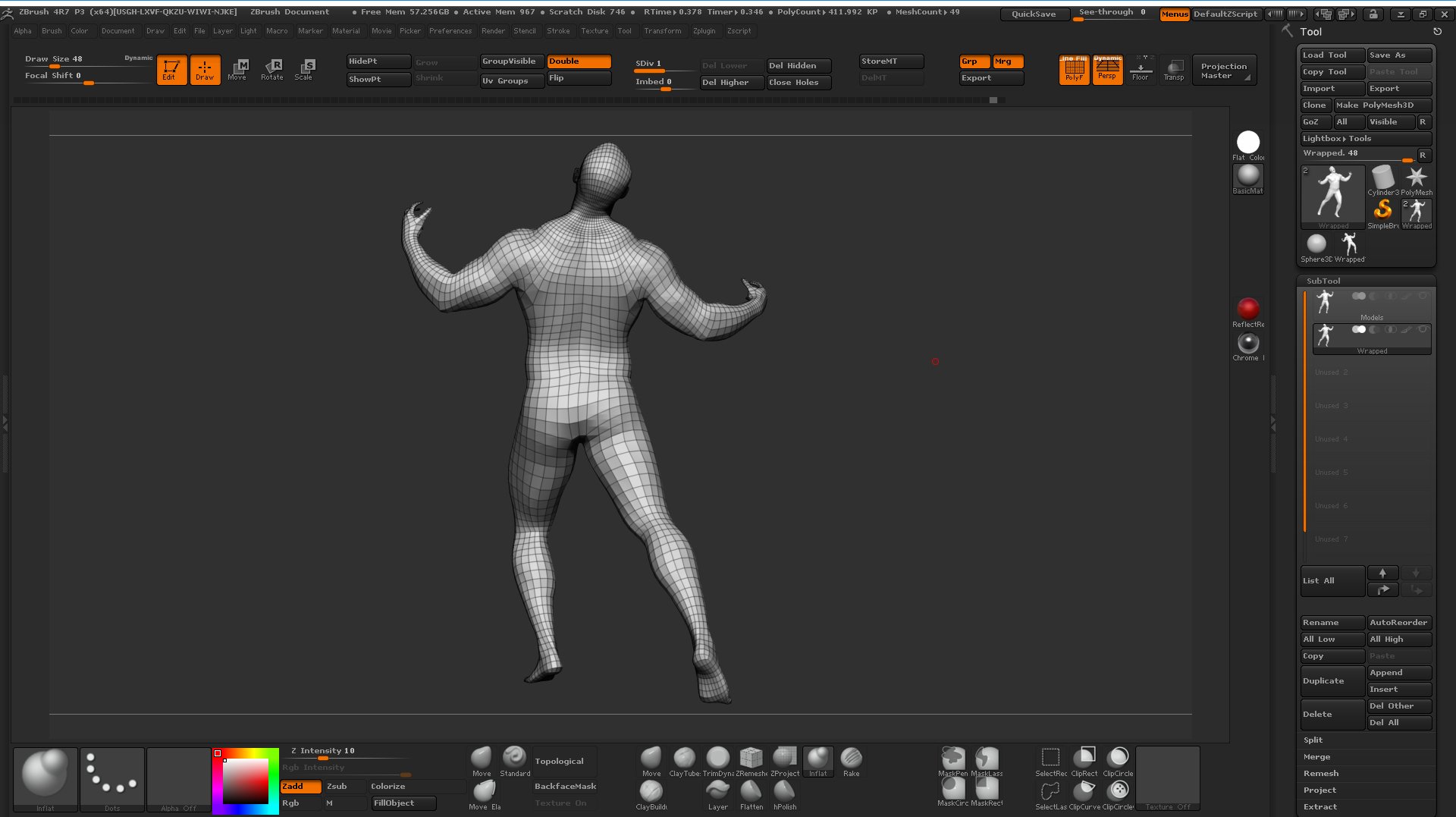
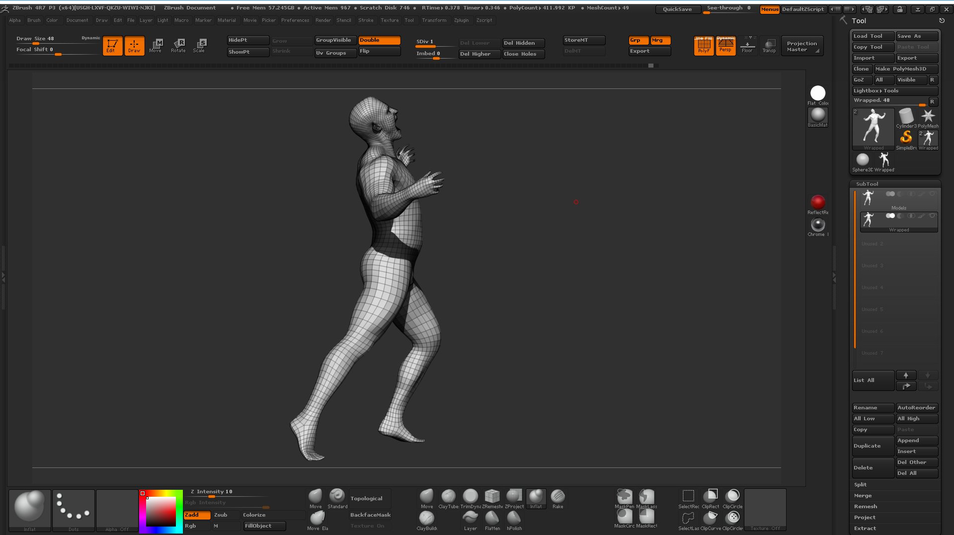
The first step is to find a base mesh. For this example, I'm using a modified version of our UV mapped symmetrical male base mesh. Images of which you can see below.
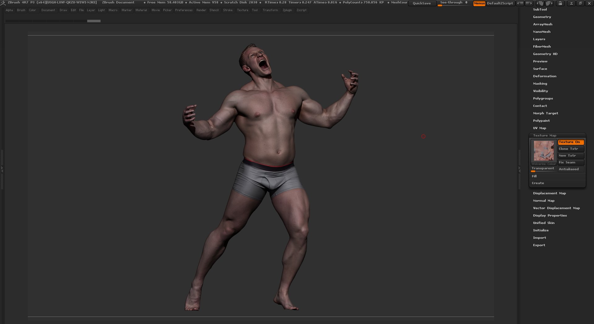
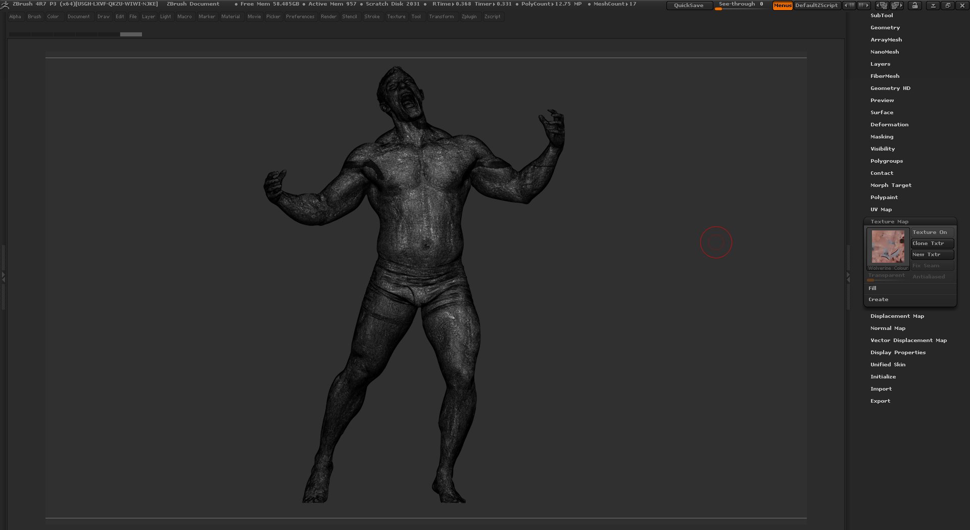
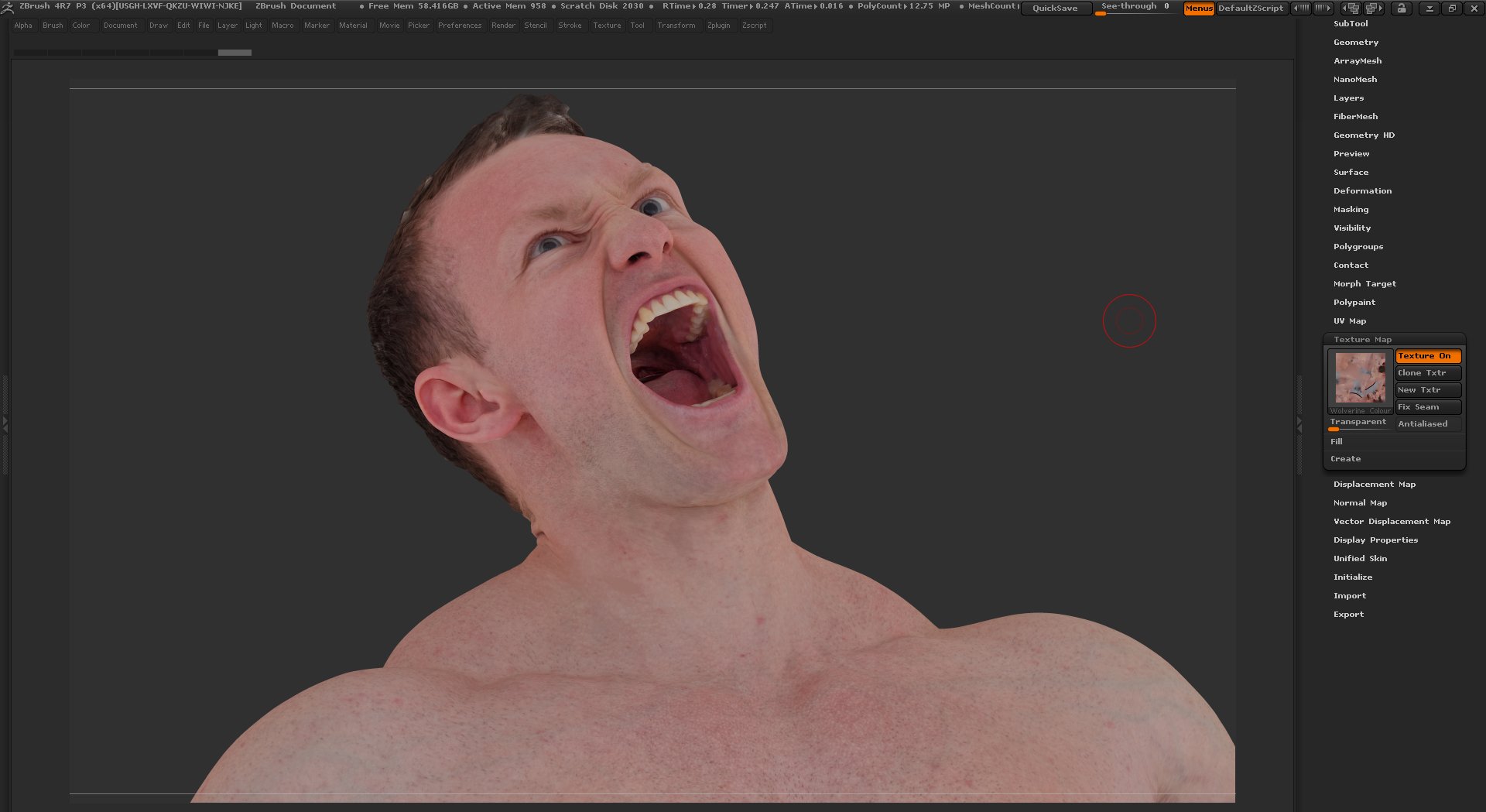
For the purposes of this tutorial, I'm going to be using one of our Bodybuilder poses, I call this one Wolverine! This is a totally RAW scan that has been decimated down to around 750k polygons so its fairly low resolution in terms of surface details but it's a complicated dynamic pose and therefore a good subject for this tutorial.
I have included a link to the final retopologised scan and texture map at the bottom of this page.
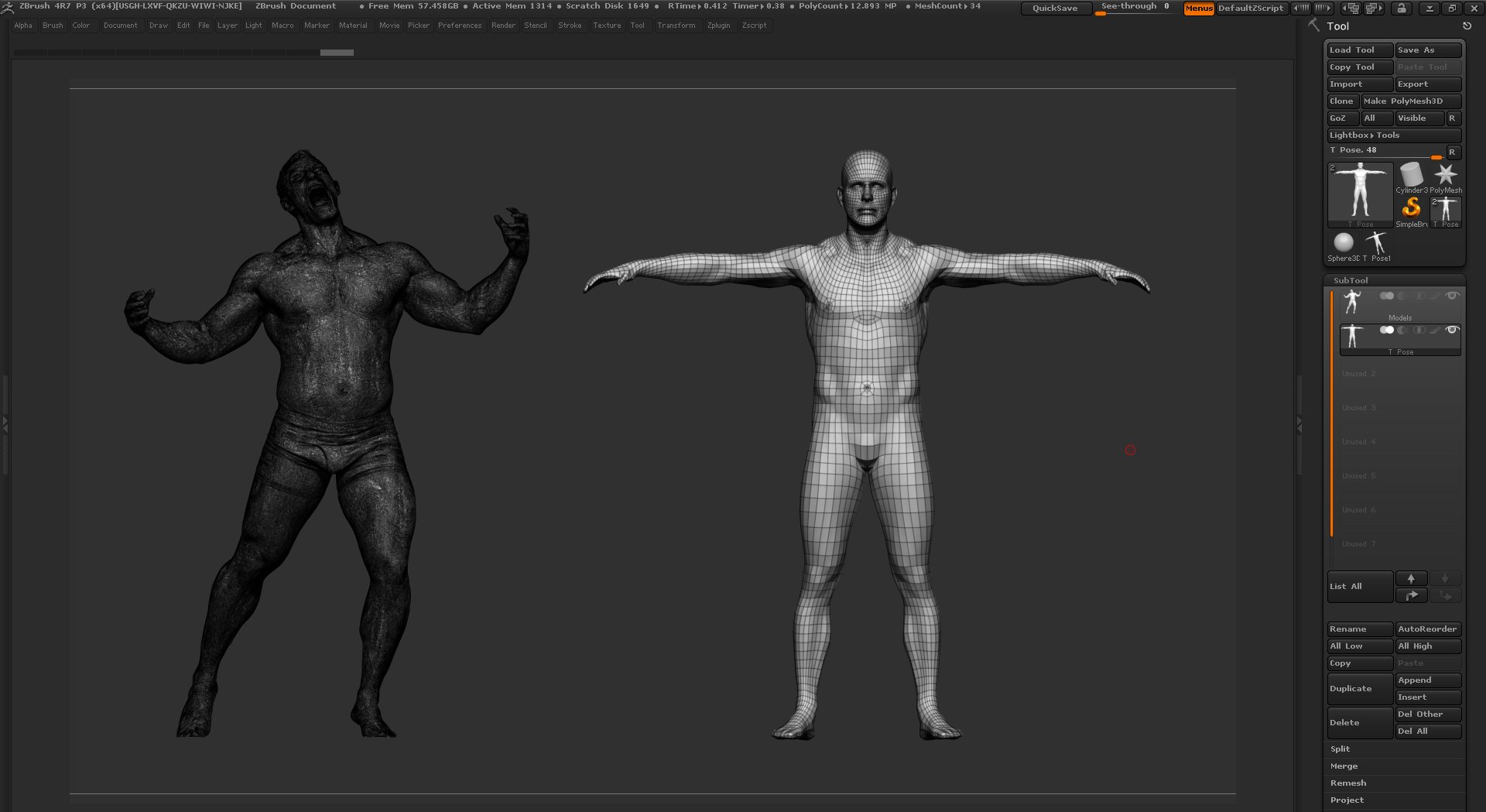
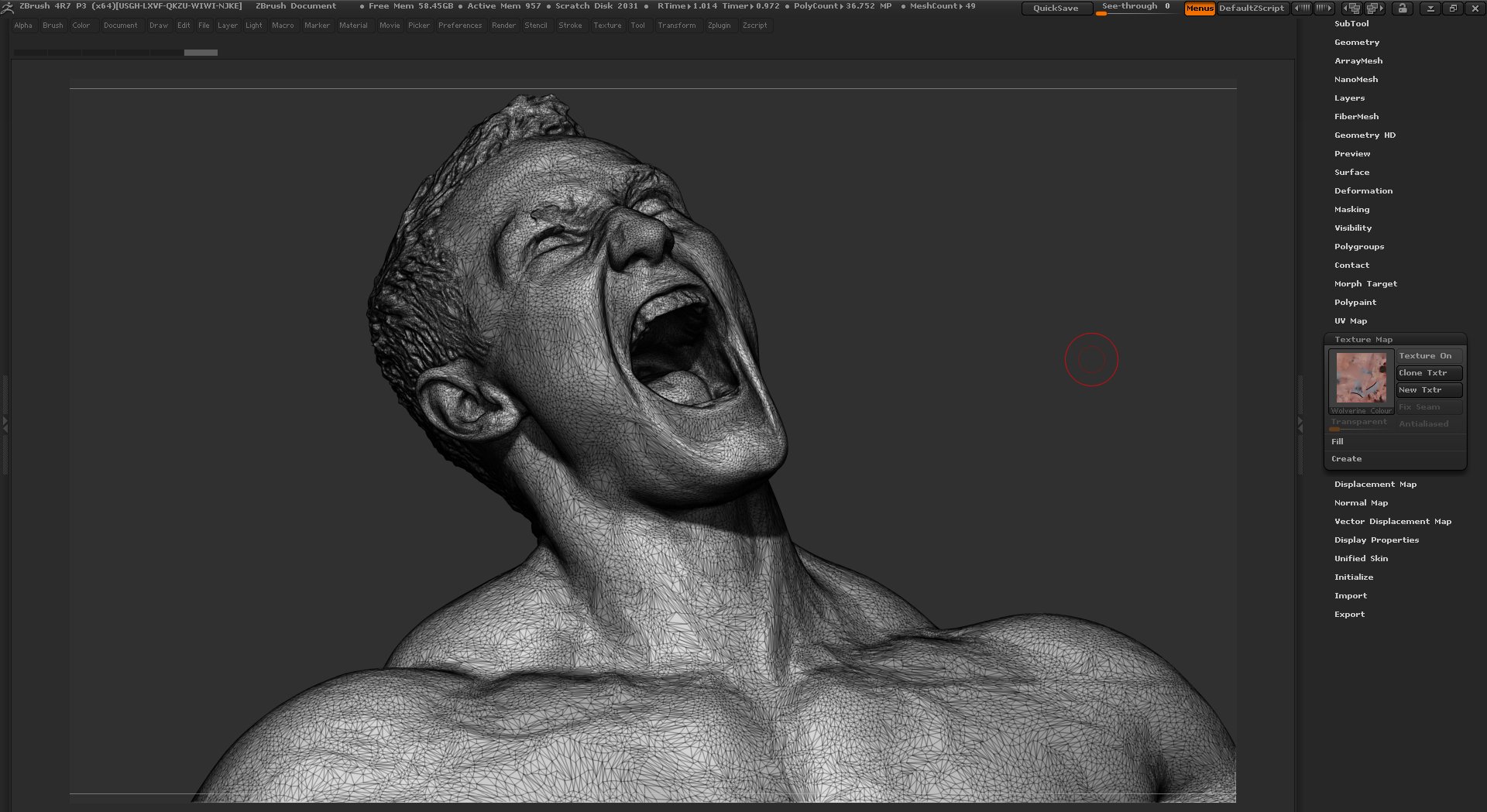
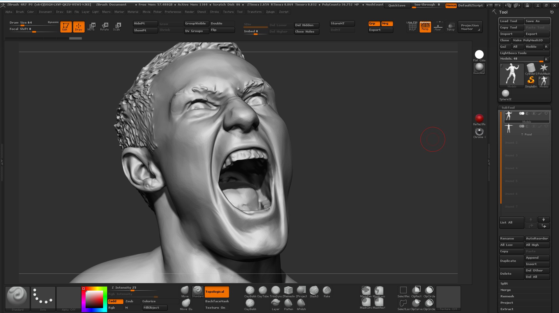
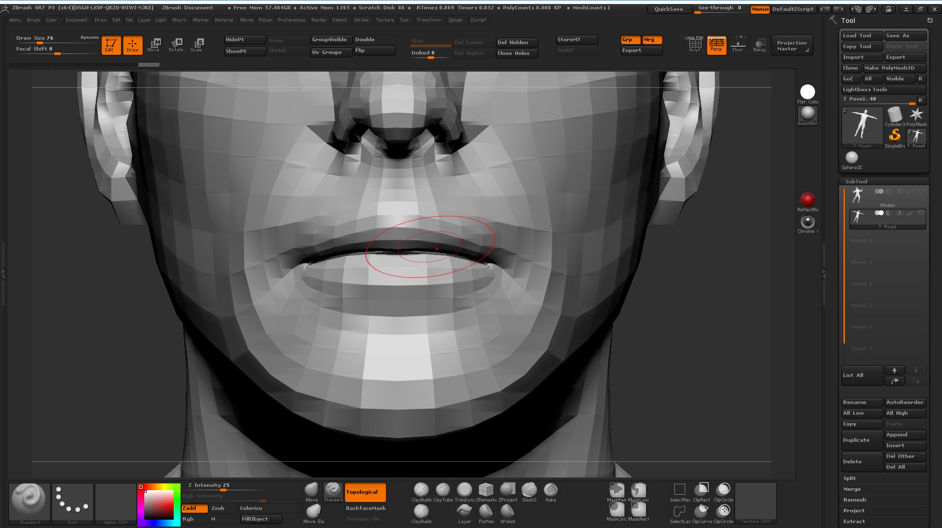
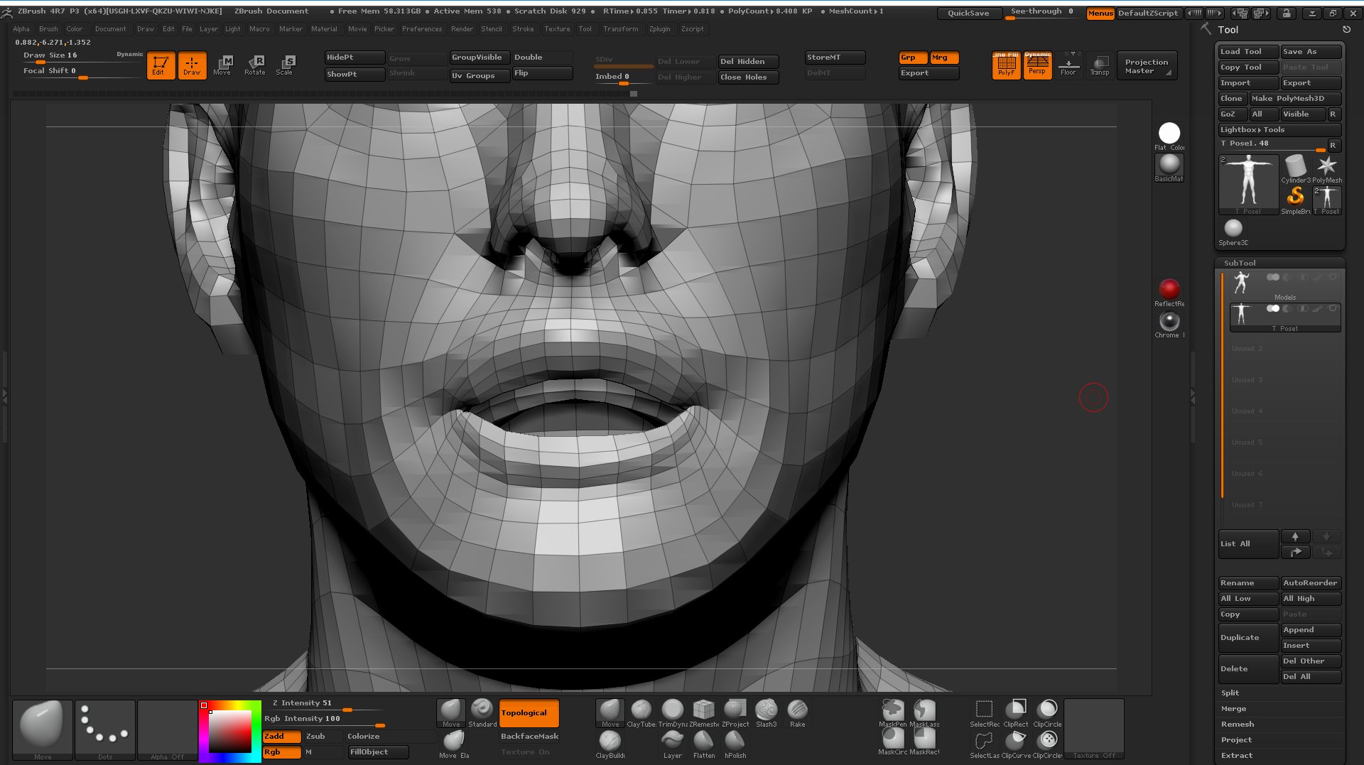
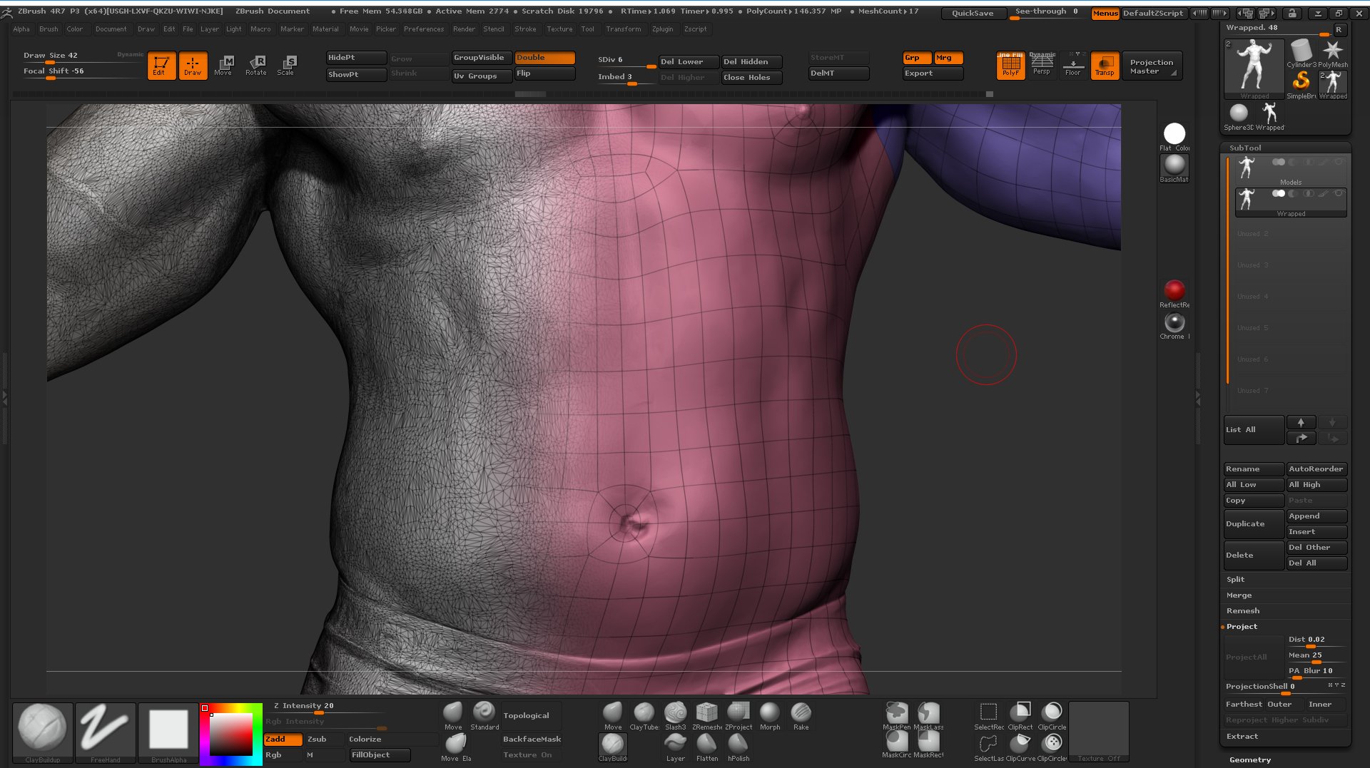
Before we load either of the models into Wrap 3 we need to make a quick adjustment to the base mesh, just to make things easier for ourselves. On the scan, you will notice this guy is having a bit of a shout, so his mouth is about as far open as it can be. When we load our base mesh into Wrap 3 we will be placing reference points to define common areas on both meshes. The base mesh has a closed mouth so the first thing we need to do is to open it a little bit in Zbrush. Not to much just slightly so we can see inside to place the reference markers in Wrap 3. The easiest way to do this is to use the move brush in Zbrush with the "Topological" option enabled as shown in the images below. "Topological" means that the brush will only affect the topology directly connected to the vertex that you select. i.e it won't pull the bottom of the mouth around when you try to move the top half. Using a fairly large brush I'm just opening the lips so I can see inside the mouth.
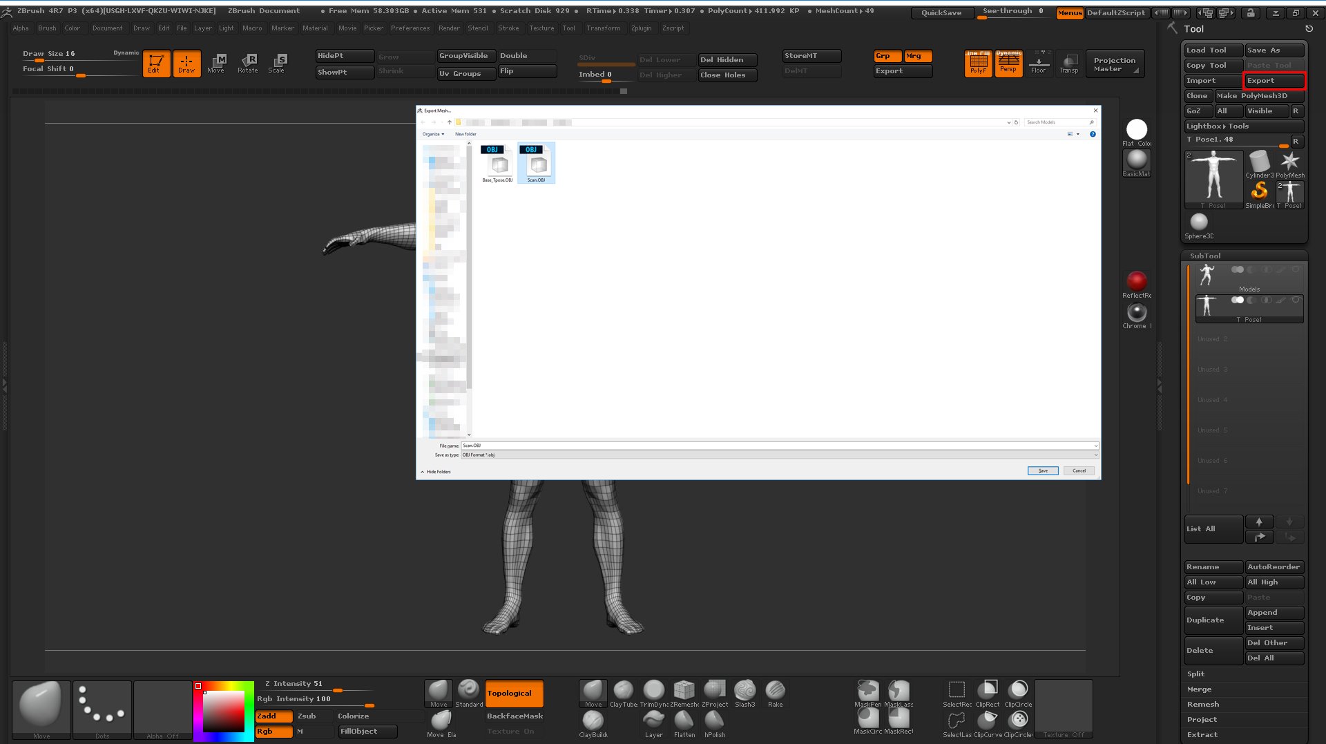
Once I'm happy with the mouth I simply export both the Decimated / RAW scan and the base mesh as OBJ's
Geometry wrapping with wrap 3
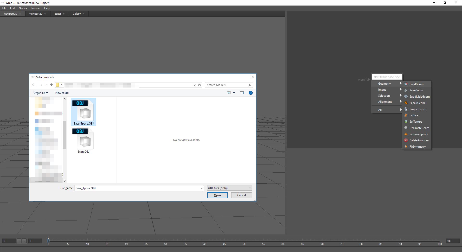
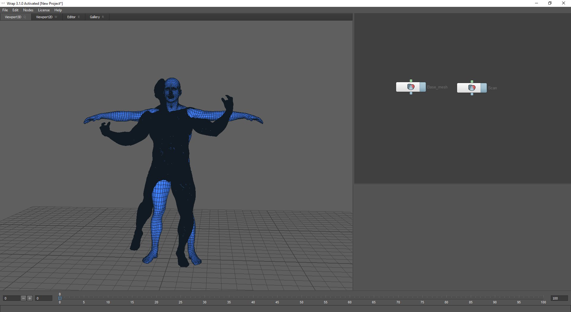
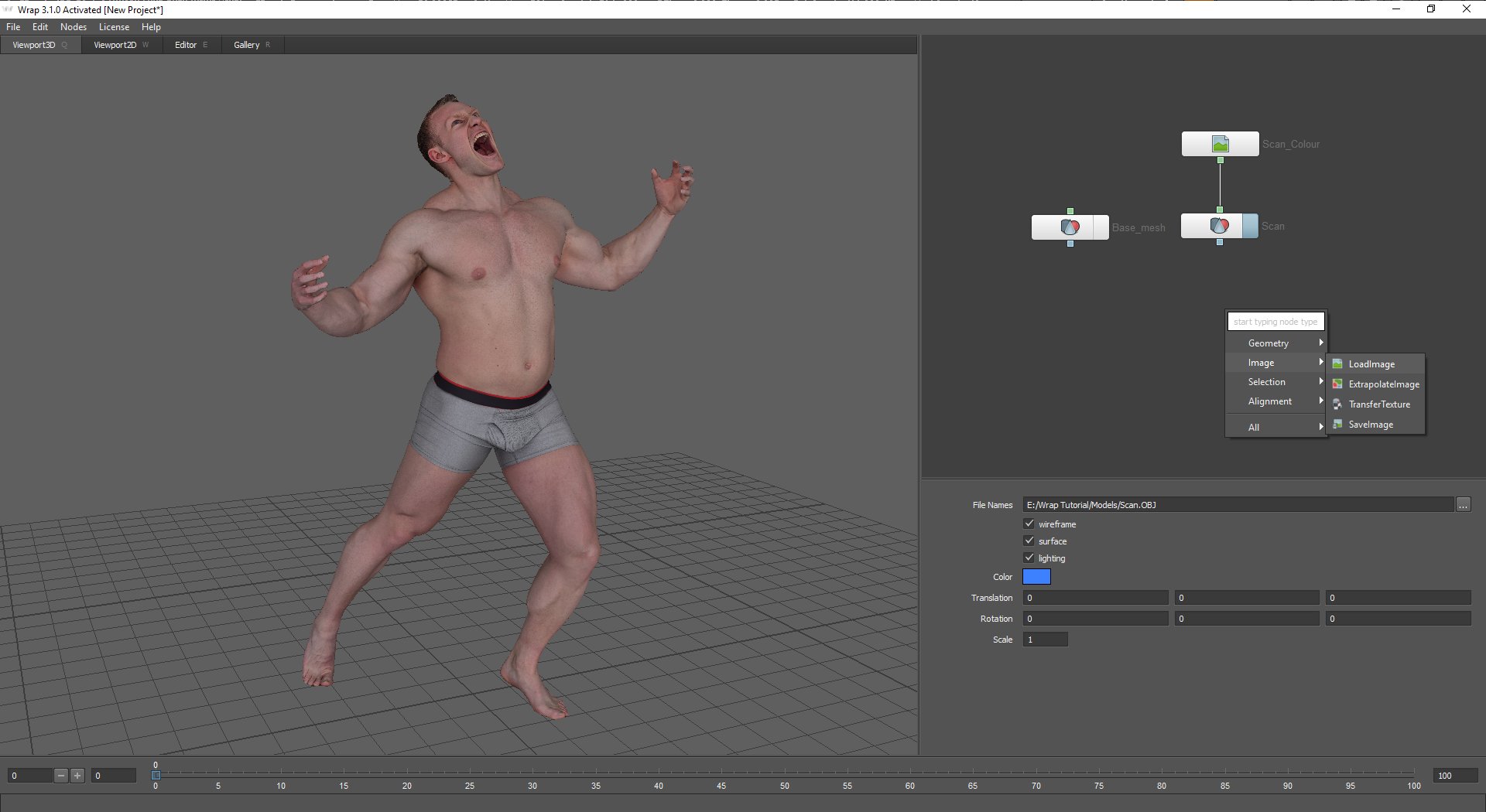
Load up Wrap 3 and use the "Tab" key on the node area on the top right of the interface, select Geometry >LoadGeom and select the exported base mesh. Do the same for the Scan data as shown in the images below
Next we need to load the scan colour map, again pressing the "Tab" key in the node box, scroll down the pop out menu and select Image > LoadImage and select the scan colour map, connect the nodes by clicking the green square at the bottom of the image map node and dragging it onto the green square at the top of the Geometry node as shown in the image below. If you're working on a non-colour scan you can completely ignore this and go straight to point selection and wrapping.
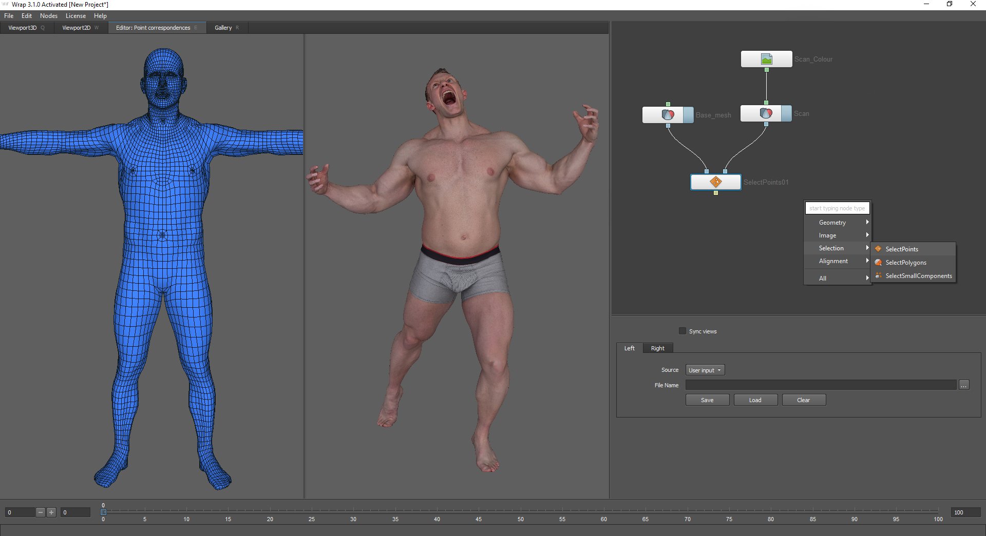
Once we have both the base mesh and the 3D scan loaded into Wrap 3 we need to start defining reference points that will tell the software how to deform the base mesh to match the contours of the scan. To do this we need to add a "Select Points" node. Press "Tab" on the nodes window and select Selection > SelectPoints. Now simply connect the Base mesh and scan geometry nodes to the select points node as shown in the image below. Clicking the "Editor : Point Corrospondencies" tab at the top of the 3d view window will give you a side by side view of the base mesh and the scan.
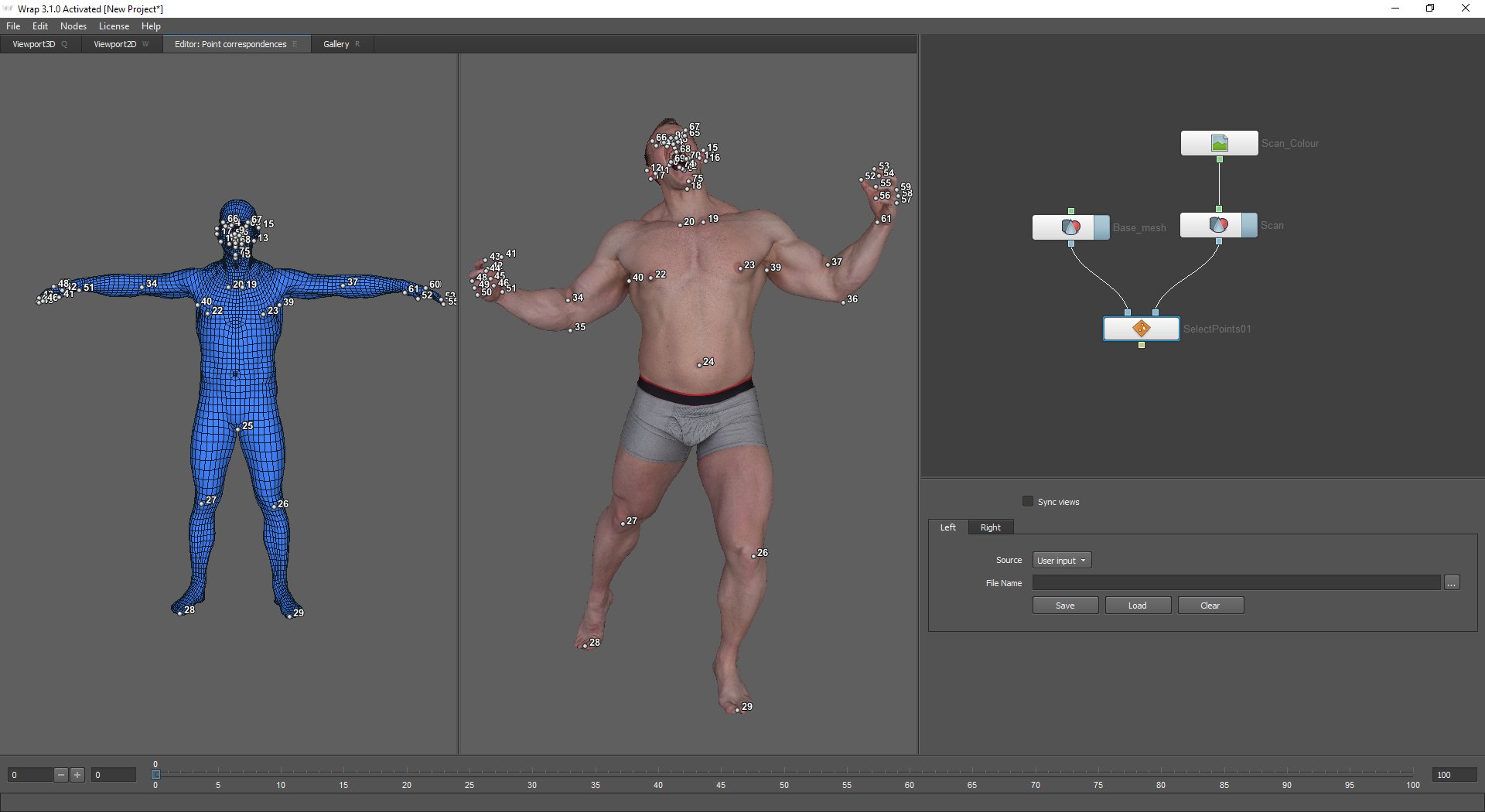
What were going to do now is select "correspondence points" on the model in order to tell the software how to deform the base mesh. The basic idea is to place points in the same location on the scan as they are on the base mesh. For example, if you put a point on the elbow of the base mesh then also place one on the elbow of the scan. Rather than trying to explain this process with images I've made a video showing the entire point selection process below. In the video I'm manually rotating the view window to find the corresponding points on each of the models, you can, however, use the "Sync Views" toggle to align the two views. This works great if the base mesh and the scan are fairly similar but in this case its easier to do it manually as the T-Pose mesh is a very different shape to the scan with areas such as the elbows and hands occupying very different areas in 3d space.
Once you are finished you should have something that looks like the image below.
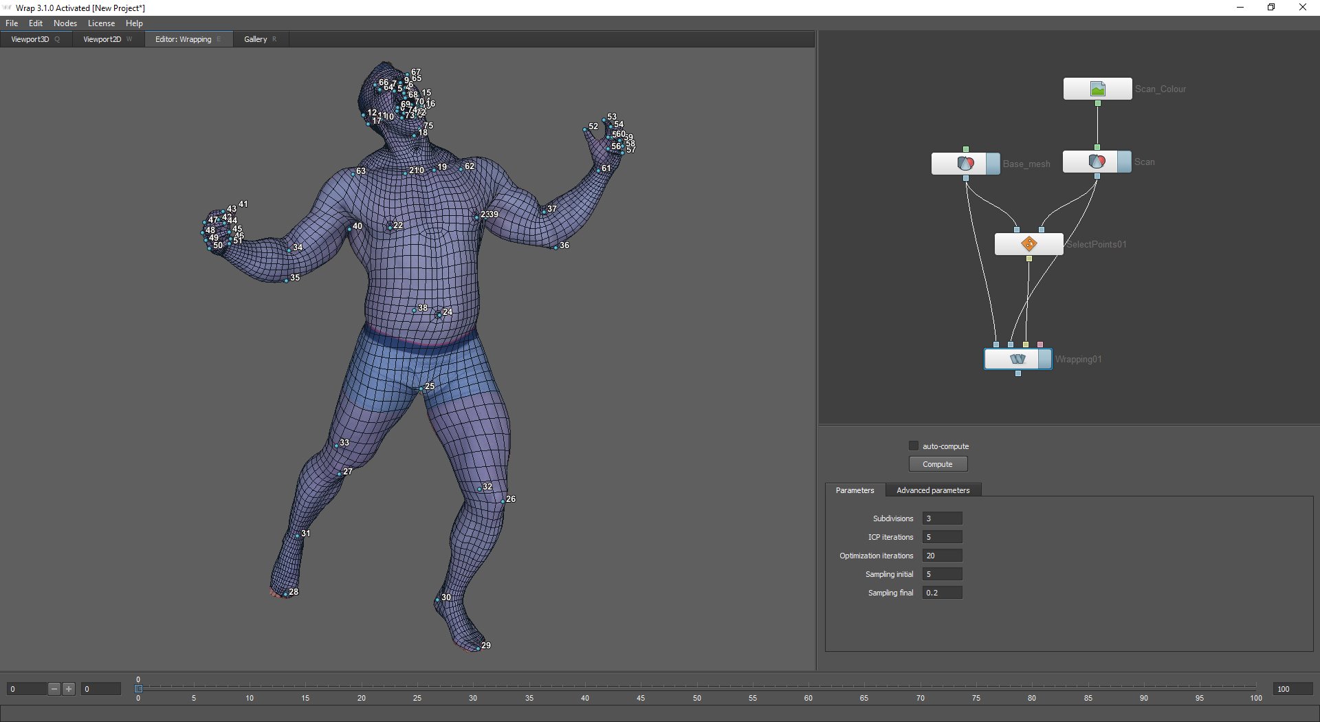
Now for the final and most exciting stage of the process, Wrapping! using the "Tab" key bring up the drop down menu in the node window and select the Alignment > Wrapping node. Connect the nodes as shown in the image below. Base mesh on the far left, Scan in the next blue connector and the select points output into the yellow connector but before you do make sure you uncheck the "auto-compute" box on the wrapping node. With this enabled, it will start to calculate the wrapping as soon as you plug in the nodes and depending on the order you do this it could cause problems.
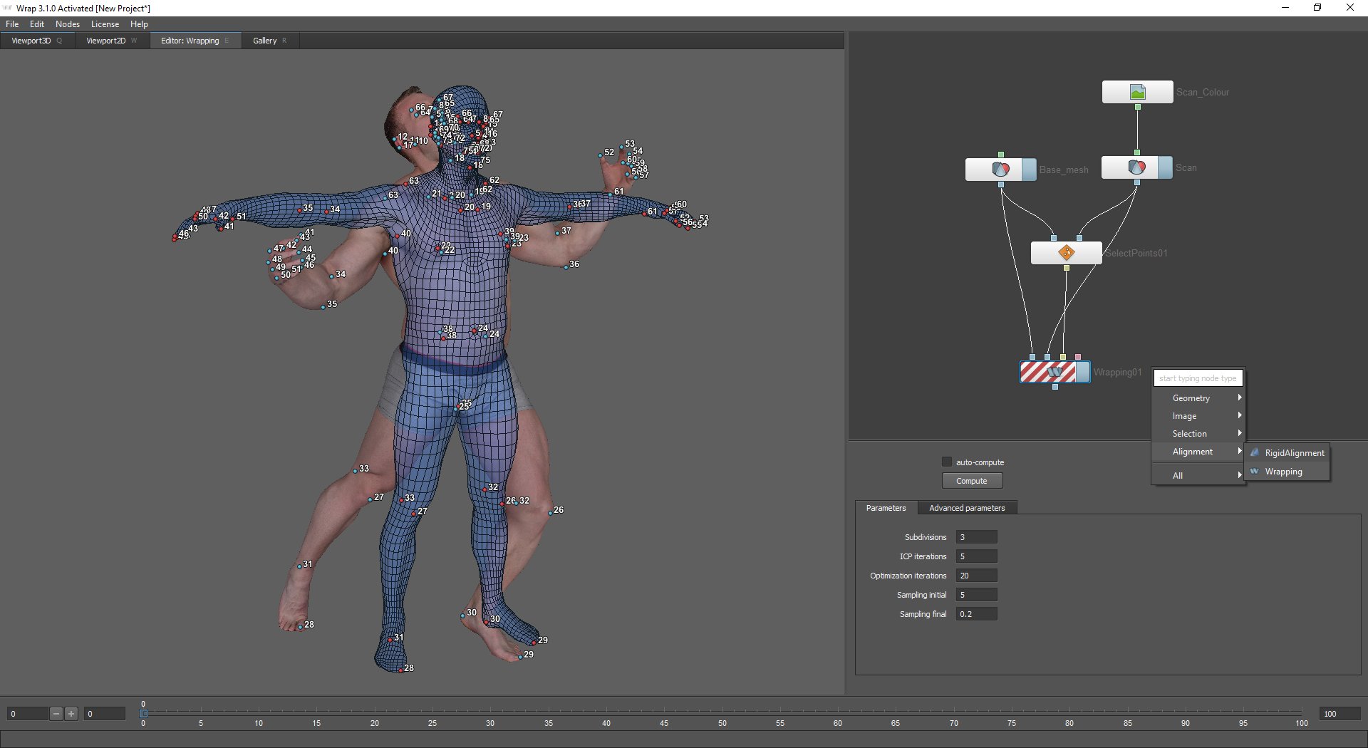
Hit the Compute button and wait for the software to perform its magic! after a few minutes, you should have something that looks like this.
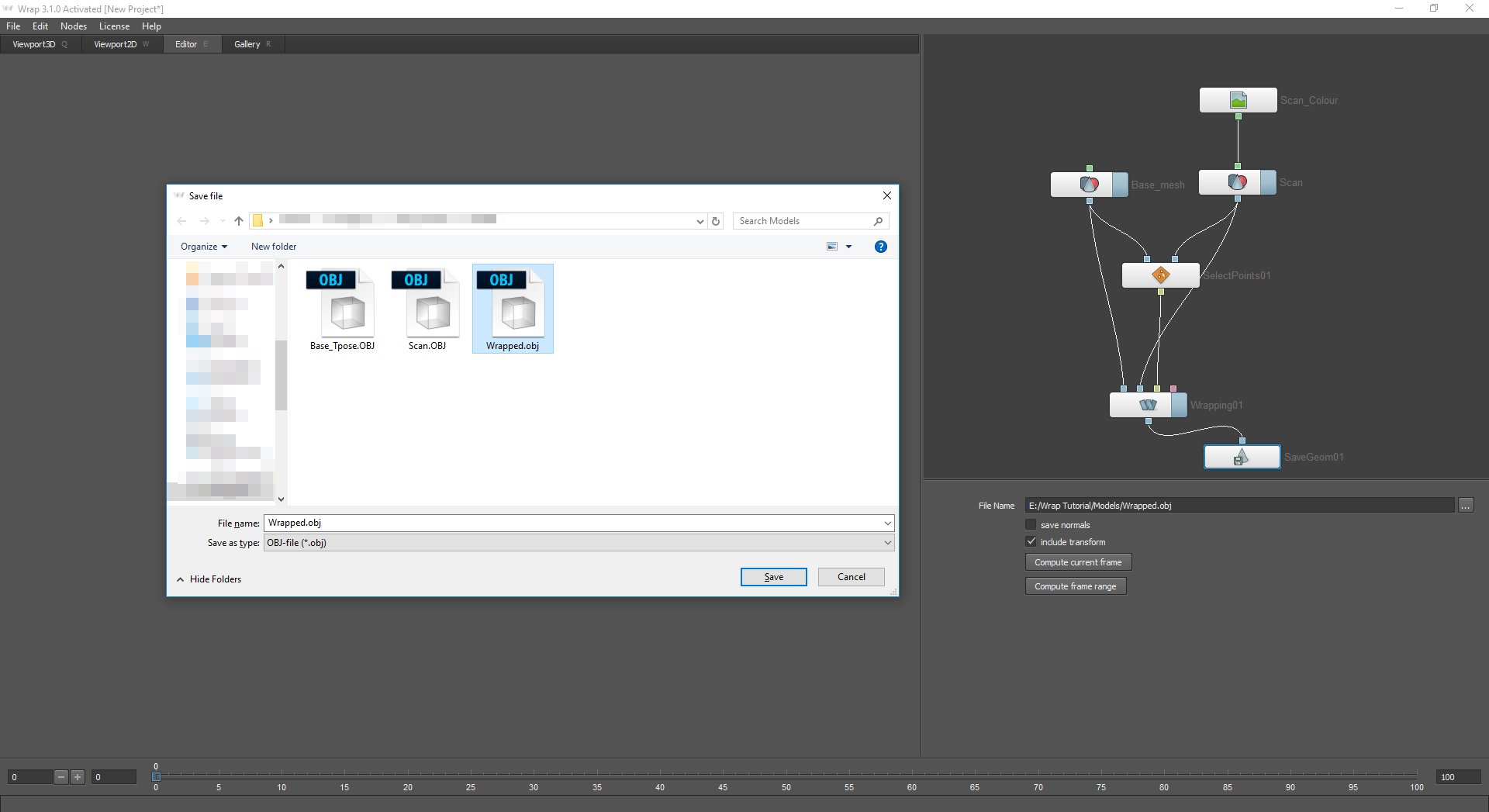
As you can see Wrap 3 has done an amazing job of the mesh now we can bring the new UV mapped wrapped base mesh back into Zbrush and project the details from the scan onto the new mesh. First of all we have to save out the wrapped topology. To do that hit "tab" in the nodes window and select Geometry > SaveGeom and connect it to the output from the wrapping node as shown in the image below. Set a file name in the properties window and hit Compute current frame.
Zbrush geometry projection
Before we transfer the texture were going to do the projecting in Zbrush. The reason being the low-resolution base mesh is always going to be slightly out of alignment with the details on the scan simply due to the lack of subdivision on the polygons and there for a bit of disparity between the profiles of the two objects. In order to fix this we're going to subdivide and project the scan back to the new wrapped base mesh and bake the texture onto a higher resolution object a bit later on.
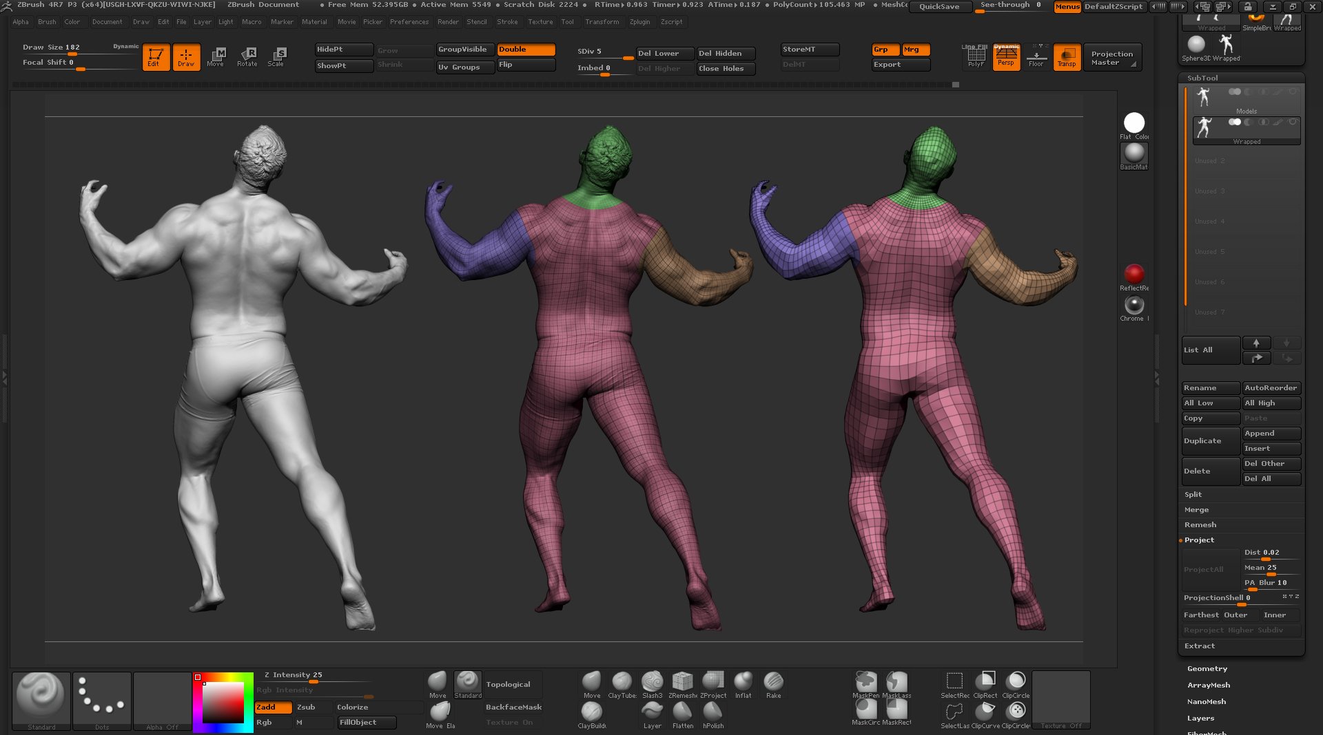
Load up ZBrush and import both the original scan and the new Wrapped mesh into the same Subtool as shown below, Note:: I have moved the models in this image to show them side by side when you import them they will come in on top of each other as in Wrap 3.
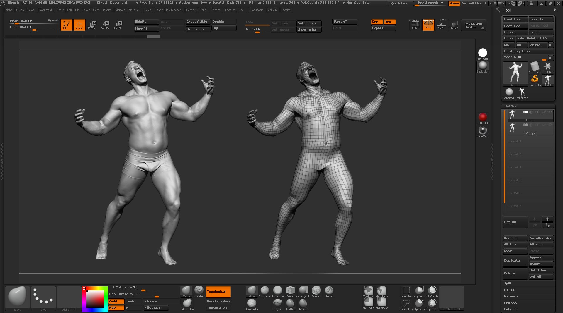
As you can see from the images below Wrap 3 has done a fantastic job of matching the base mesh to the scan
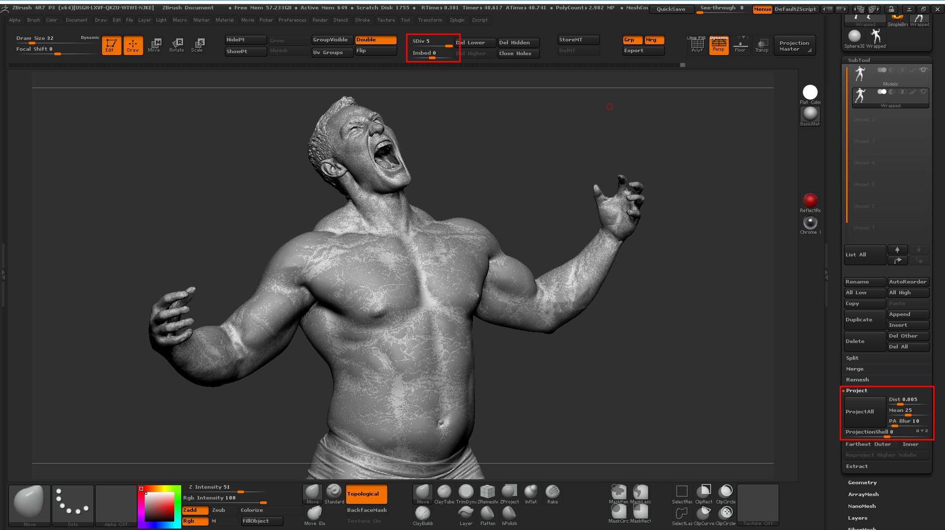
We're going to do two projections in order to get the details from the scan back onto the base mesh. For the first projection subdivide the model once up to level 2 set the projection distance to 0.005 and hit the ProjectAll button as shown below
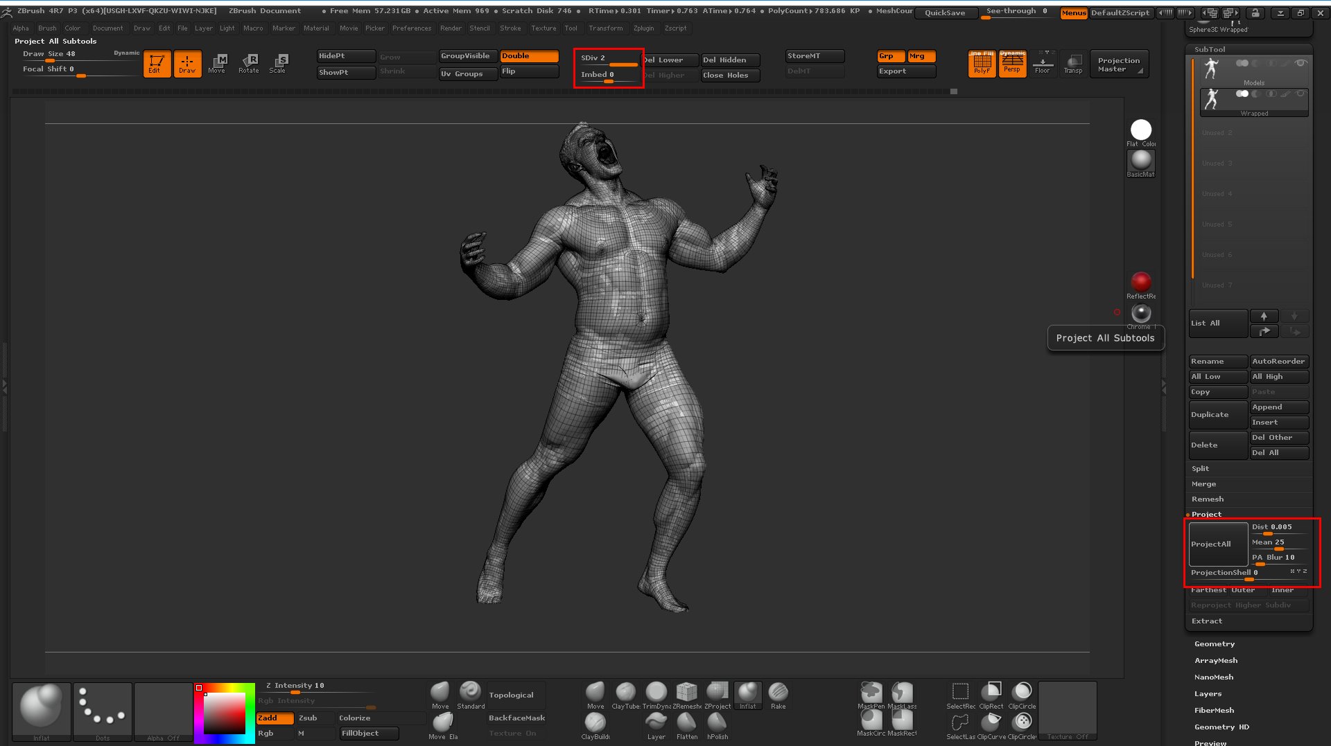
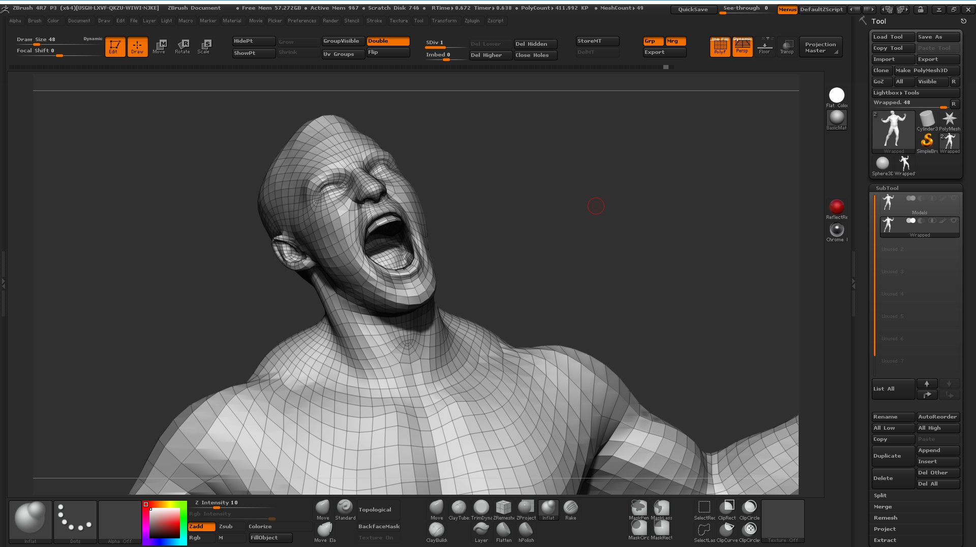
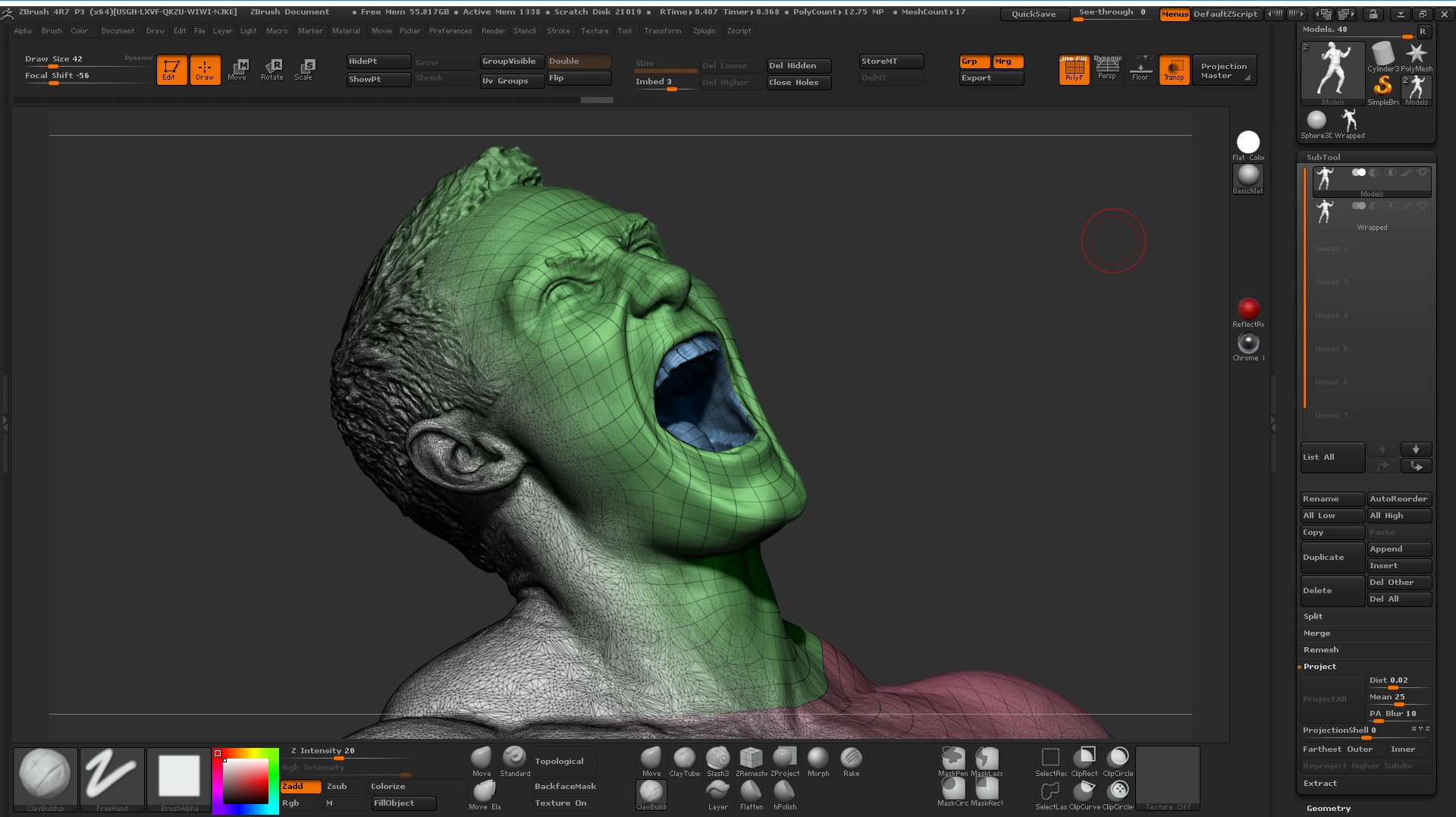
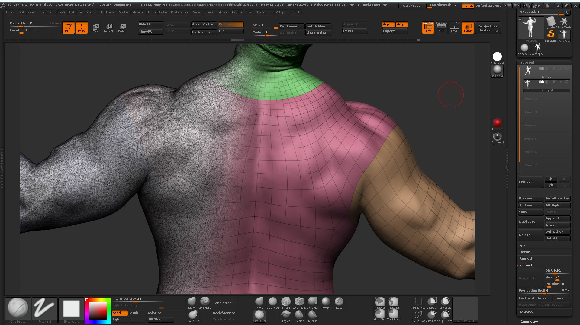
Now subdivide the model all the way up to level 5 and with the same projection settings hit the ProjectAll button again and you should end up with something like the image below.
You will now see that you have a perfectly re-topologised model with all the details from the original scan projected onto the level 5 subdivision model complete with UV's
Texture baking in Wrap 3
Once the geometry projection process is complete with can begin the process of projecting the texture from the scan onto the new topology. As I mentioned before its best to do this on a higher subdivision level of the mesh because the profile of the polygons will be more in keeping with the original scan than if we used the lowest resolution SubD level 1 mesh.
For this example, I'm exporting a SubD level 3 object from Zbrush. and loading that along with the original scan into Wrap 3. Using the now familiar node window set up your nodes as shown in the window below. We will be using Image > TransferTexture to bake the texture from the scan onto the clean mesh and then the Image > SaveImage node to save out the resulting baked texture map. You will also notice the Extrapolate image node after the TransferTexture. It's very important that we include this node in the image transfer network. The Extrapolate image node will expand the image borders around the UV shells which means we won't get any nasty edges or seams on or around the UV borders on the mesh.
To set the size of the exported map simple enter the pixel dimensions into the TextureTransfer nodes properties window. Here I'm using 10,000 x 10,000 pixels.
![]()
Hit the compute current frame button on the SaveImage node and you should end up with something that looks like the image below. Obviously, your base mesh may have a very different UV layout to the one I'm using here.
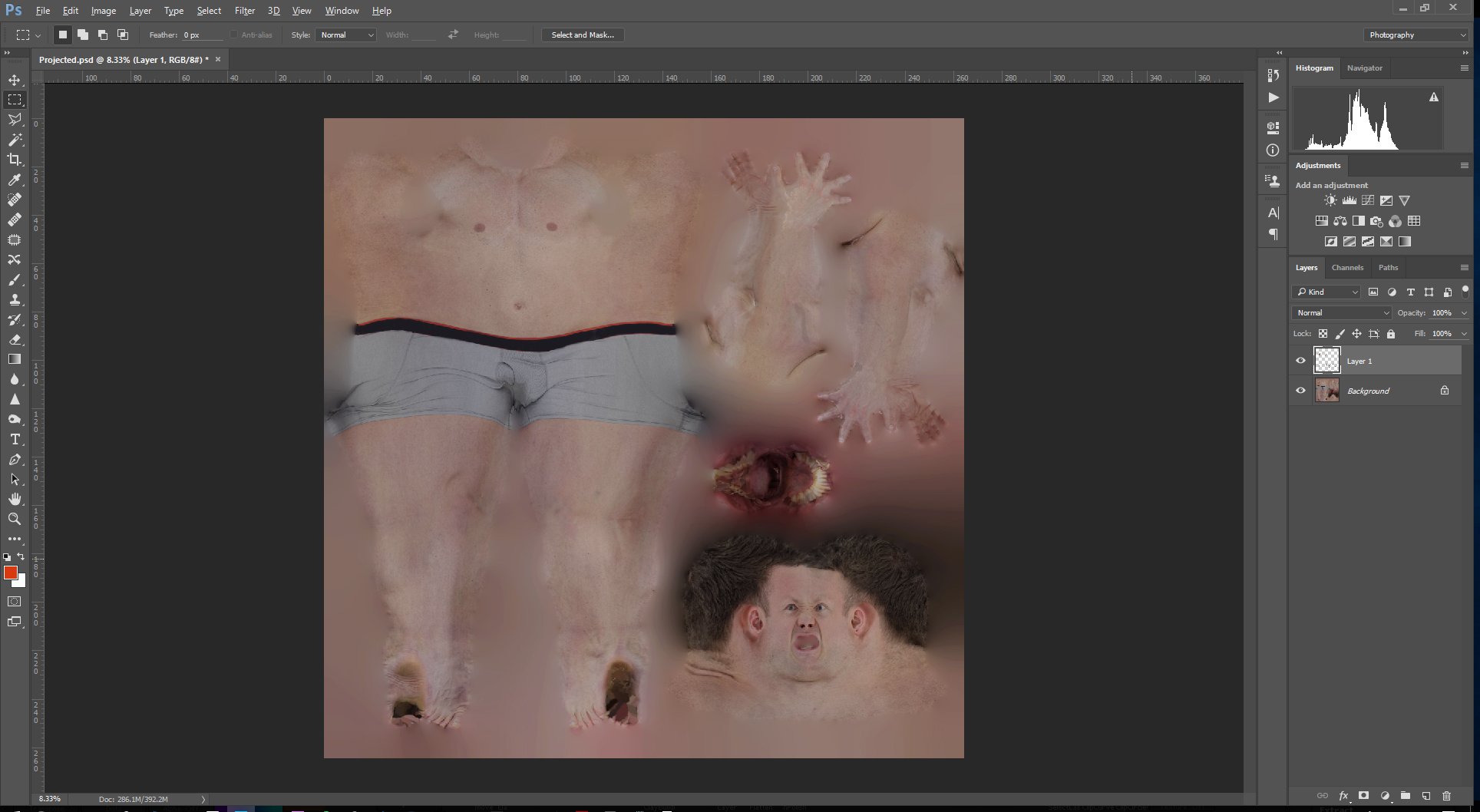
And that's it! It's a fairly simple and straightforward process and a great way of re-topologising 3d scans. For me, one of the major benefits of this technique is having the ability to go from a messy scanned mesh to a clean projected mesh in about 20 minutes. When it comes to cleanup and post processing working with a nice clean quadded base is much easier than trying to remove noise or sculpt details onto a RAW scan or even a dynameshed or Zremeshed scan.